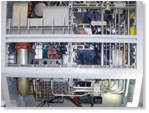
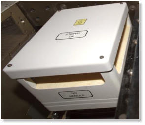
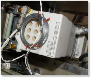
US Laboratory Avionics Air Assembly Fan

Copyright © 1998-2020 acoutek LLC


Applications
Limiting acoustic exposure levels in crew
compartments and habitats is essential to
achieve safe, functional, effective, and
comfortable acoustic environments for the
crew members during space operations.
Acoutek LLC (GT*) supported several noise
control applications to meet acoustic
requirements in space crew compartments,
and/or documented the design approaches
and highlighted their acoustic benefits.
Unique multi-function
muffler design
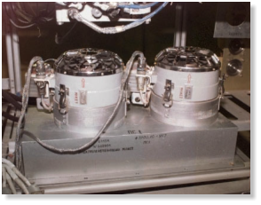
Multi-functional air filtration muffler The Zarya control module, also known by the technical term Functional Cargo Block (FGB), was the first International Space Station (ISS) element placed in space and provided the "foundation" for assembly of the other ISS elements. The FGB features an air filtration system of which the two inlets, one on each side of the cabin, have filters that remove dust-type particles from the module’s atmosphere. Behind each inlet are two encased, two-bladed fans, which circulate the air. FGB air filtration fans Noise generated by the air filtration system exceeded the continuous noise criteria in the octave bands from 250 Hz to 8000 Hz. To attenuate the noise Acoutek LLC (GT) designed a unique muffler under sub- contract. The innovative concept included noise transmission loss, structural damping, acoustic absorption, tone attenuation and flow guidance. Acoustic foam and Helmholtz resonator applications Temperature and effective length of the resonator inlet were recognized as uncertainties in the acoustic performance of the muffler. Variable length bushings were used to allow tuning of the muffler and maximize the Helmholtz resonator efficiency after installation. NASA built a prototype for testing. Broadband and narrow band noise insertion loss measurements were conducted validating the muffler as an effective noise abatement tool for the ISS air filtration system. (Grosveld, Ferdinand W., Goodman, Jerry R., “Design of an Acoustic Muffler Prototype for an Air Filtration Inlet on International Space Station,” Noise-Con 2003, the 2003 National Conference on Noise Control Engineering, Cleveland, Ohio, 23-25 June 2003)
Quieting of the US Airlock
depressurization pump
and heat exchanger
Depressurization pump inlet muffler The Joint Airlock is a pressurized flight element consisting of two cylindrical chambers attached end-to-end by a connecting bulkhead and hatch. The US Airlock is the primary path for the ISS space walk entry and departure for US extravehicular mobility units (EMU) and support the Russian Orlan spacesuit for extravehicular activities (EVA). Testing had indicated that the acoustic requirements for the depressurization pump, which feature a muffler on the outlet but not on the inlet, were not met. Acoutek LLC (GT) documented the approach of a Boeing developed quieting kit and highlighted its acoustic benefits. In an attempt to meet permissible noise levels an airlock “quieting kit” was developed and implemented as Government Furnished Equipment (GFE). In addition, a muffler was designed for the airlock pump inlet. Acoustic covers were applied to water and air lines with hook-and-loop fasteners to reduce flow noise. Vehicle close-out panels, which access the airlock depressurization pump installation, were treated with acoustic seal and foam applications. Depressurization pump in acoustic enclosure The most important noise reduction feature of the quieting kit was the use of vibration isolators. The isolators were used with a snubbing washer to ensure that the isolator retained good structural load capabilities in tension. The bottom of the metal enclosure box was mated to the base plate. Cut-outs in the box were minimal and consisted of pump installation clearances, and variances in pump hardware and drawings. The seals between the top and bottom were verified to be acoustically effective. To block and absorb pump-radiated noise, an acoustic enclosure was constructed with the six sides consisting of acoustic foam and barrier material between meta-aramid liners. Measurements showed that 24 dB attenuation was achieved by installing the newly designed muffler and the overall power watt level was attenuated by 23 dB after installation of the quieting kit. These improvements allowed exposure to this intermittent noise for 20 minutes during each 24-hour period. (Grosveld, Ferdinand W., Goodman, Jerry R., and Pilkinton, Gregory D., “International Space Station Acoustic Noise Control - Case Studies,” Noise-Con 2003, the 2003 National Conference on Noise Control Engineering, Cleveland, Ohio, 23-25 June 2003)
Microgravity Science
Glovebox (MSG)
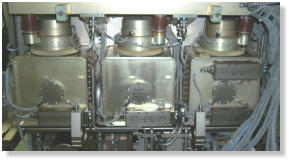
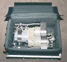
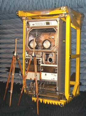
MSG flight unit rack The Microgravity Science Glovebox (MSG) is a joint development project between NASA and the European Space Agency (ESA). The facility provides a large enclosed work volume (WV), power, video, photography, vacuum connections, heat rejection, stowage, filtered air, gaseous nitrogen, lighting, airlock access, physical positioning and hold-down attachments, and computer data acquisition and control capabilities. Crew access to the WV and operational manipulation of the experiments is through sealed glove ports. The sealed mode of operation and the air circulation provide two levels of containment. Air circulation is provided by the air-handling unit (AHU), which contains three fans that draw air from the WV through three filter banks. MSG air handling units The air is then blown through the heat exchanger, the process control valves and into the air discharge duct, where it is redirected towards the WV. The avionics air assembly (AAA) provides cooling for the rack. The AAA and the AHU were computer controlled at variable fan speed settings. Measurements indicated that acoustic noise levels of the MSG rack were well above the NC-40 criterion for continuous noise level limits of an integrated rack. Rear view of the MSG (back panels removed) Acoutek LLC (GT) supported several different noise control measures applied to the MSG rack to lower the acoustic noise emission. Contoured one-inch thick acoustic foam absorption material was attached to the side, top and back skin panels, while the bottom was covered with five-inch thick pyramidal foam. Visco-elastic damping materials were used to reduce resonant panel noise radiation. Gaps were closed with tape or silicone rubber materials. Acoustic foam mufflers were applied to the air handlers and the AAA air inlet duct. Mass-loaded barrier materials were used to wrap hoses and isolate noise sources. The AHU units, which were originally made of sheet metal, were replaced by custom- designed and fully milled units. The fan blades received aerodynamic contours and the number of blades were changed from 6/8/6 to 7/8/9. The inlet was smoothed out aerodynamically. The central rotor axle geometry was optimized to allow a smooth airflow in the narrow central section. Most noise reduction was achieved by different bend geometry of the air outlet housing after the second stage rotor. The new AHU fans were statically and dynamically balanced. The AAA fans were retrofitted with new bearings of a different material to remedy an anomaly that had resulted in a ticking noise during acoustic testing. At verification testing for flight, acoustic sound pressure levels at 0.6 meter from the MSG rack measured less than the NC-40 requirements, except for a 2.1 dB exceedance in the 500 Hz octave band. An exception request for this exceedance was submitted and subsequently approved. (Grosveld, Ferdinand W., Goodman, Jerry R., and Pilkinton, Gregory D., “International Space Station Acoustic Noise Control - Case Studies,” Noise-Con 2003, the 2003 National Conference on Noise Control Engineering, Cleveland, Ohio, 23-25 June 2003) * Grosveld Technologies

AAA fan acoustic features
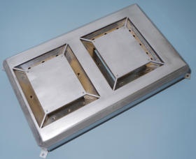
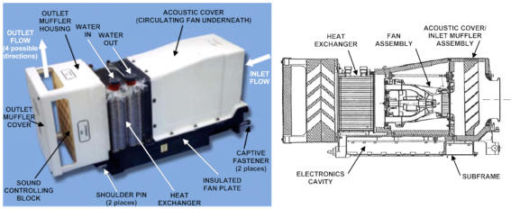
Avionics and experiments producing heat and requiring cooling are located in compartmentized
racks. Cooling is provided by forced air from the Avionics Air Assembly (AAA) fan and heat
exchanger through the avionics air loop. NASA developed noise control measures to mitigate
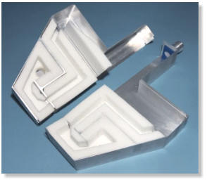
excessive sound from these units by installing a noise barrier cover and fan plate. The AAA fan is
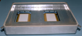
soft-mounted inside its assembly with isolation or anti-vibration mounts. Chevron-shaped holes
are carved into acoustic foam for air flow through the inlet and outlet mufflers (precluding direct
line-of-sight flow). The end plate at the fan outlet, diverting the flow outwards, is also covered with
acoustic foam. Acoutek LLC (GT) provided documentation and highlighted the acoustic benefits of
the noise control measures.
(Grosveld, Ferdinand W. and Goodman, Jerry R., “Noise Control in Habitable Space Vehicles and Enclosures,” Proceedings of the
Third IAASS Conference, Rome, Italy, 21-23 October 2008)
AAA fan foam inlet (left) and outlet
Applications
Limiting acoustic exposure levels in crew compartments and habitats is
essential to achieve safe, functional, effective, and comfortable acoustic
environments for the crew members during space operations. Acoutek
LLC (GT*) supported several noise control applications to meet acoustic
requirements in space crew compartments, and/or documented the
design approaches and highlighted their acoustic benefits.
Unique multi-function
muffler design
Multi-functional air filtration muffler The Zarya control module, also known by the technical term Functional Cargo Block (FGB), was the first International Space Station (ISS) element placed in space and provided the "foundation" for assembly of the other ISS elements. The FGB features an air filtration system of which the two inlets, one on each side of the cabin, have filters that remove dust-type particles from the module’s atmosphere. Behind each inlet are two encased, two-bladed fans, which circulate the air. FGB air filtration fans Noise generated by the air filtration system exceeded the continuous noise criteria in the octave bands from 250 Hz to 8000 Hz. To attenuate the noise Acoutek LLC (GT) designed a unique muffler under sub-contract. The innovative concept included noise transmission loss, structural damping, acoustic absorption, tone attenuation and flow guidance. Acoustic foam and Helmholtz resonator applications Temperature and effective length of the resonator inlet were recognized as uncertainties in the acoustic performance of the muffler. Variable length bushings were used to allow tuning of the muffler and maximize the Helmholtz resonator efficiency after installation. NASA built a prototype for testing. Broadband and narrow band noise insertion loss measurements were conducted validating the muffler as an effective noise abatement tool for the ISS air filtration system. (Grosveld, Ferdinand W., Goodman, Jerry R., “Design of an Acoustic Muffler Prototype for an Air Filtration Inlet on International Space Station,” Noise-Con 2003, the 2003 National Conference on Noise Control Engineering, Cleveland, Ohio, 23-25 June 2003)
Quieting of the US Airlock
depressurization pump and heat
exchanger
Depressurization pump inlet muffler The Joint Airlock is a pressurized flight element consisting of two cylindrical chambers attached end- to-end by a connecting bulkhead and hatch. The US Airlock is the primary path for the ISS space walk entry and departure for US extravehicular mobility units (EMU) and support the Russian Orlan spacesuit for extravehicular activities (EVA). Testing had indicated that the acoustic requirements for the depressurization pump, which feature a muffler on the outlet but not on the inlet, were not met. Acoutek LLC (GT) documented the approach of a Boeing developed quieting kit and highlighted its acoustic benefits. In an attempt to meet permissible noise levels an airlock “quieting kit” was developed and implemented as Government Furnished Equipment (GFE). In addition, a muffler was designed for the airlock pump inlet. Acoustic covers were applied to water and air lines with hook-and-loop fasteners to reduce flow noise. Vehicle close-out panels, which access the airlock depressurization pump installation, were treated with acoustic seal and foam applications. Depressurization pump in acoustic enclosure The most important noise reduction feature of the quieting kit was the use of vibration isolators. The isolators were used with a snubbing washer to ensure that the isolator retained good structural load capabilities in tension. The bottom of the metal enclosure box was mated to the base plate. Cut-outs in the box were minimal and consisted of pump installation clearances, and variances in pump hardware and drawings. The seals between the top and bottom were verified to be acoustically effective. To block and absorb pump- radiated noise, an acoustic enclosure was constructed with the six sides consisting of acoustic foam and barrier material between meta-aramid liners. Measurements showed that 24 dB attenuation was achieved by installing the newly designed muffler and the overall power watt level was attenuated by 23 dB after installation of the quieting kit. These improvements allowed exposure to this intermittent noise for 20 minutes during each 24-hour period. (Grosveld, Ferdinand W., Goodman, Jerry R., and Pilkinton, Gregory D., “International Space Station Acoustic Noise Control - Case Studies,” Noise-Con 2003, the 2003 National Conference on Noise Control Engineering, Cleveland, Ohio, 23-25 June 2003)
Microgravity Science
Glovebox (MSG)
MSG flight unit rack The Microgravity Science Glovebox (MSG) is a joint development project between NASA and the European Space Agency (ESA). The facility provides a large enclosed work volume (WV), power, video, photography, vacuum connections, heat rejection, stowage, filtered air, gaseous nitrogen, lighting, airlock access, physical positioning and hold-down attachments, and computer data acquisition and control capabilities. Crew access to the WV and operational manipulation of the experiments is through sealed glove ports. The sealed mode of operation and the air circulation provide two levels of containment. Air circulation is provided by the air- handling unit (AHU), which contains three fans that draw air from the WV through three filter banks. MSG air handling units The air is then blown through the heat exchanger, the process control valves and into the air discharge duct, where it is redirected towards the WV. The avionics air assembly (AAA) provides cooling for the rack. The AAA and the AHU were computer controlled at variable fan speed settings. Measurements indicated that acoustic noise levels of the MSG rack were well above the NC-40 criterion for continuous noise level limits of an integrated rack. Rear view of the MSG (back panels removed) Acoutek LLC (GT) supported several different noise control measures applied to the MSG rack to lower the acoustic noise emission. Contoured one-inch thick acoustic foam absorption material was attached to the side, top and back skin panels, while the bottom was covered with five-inch thick pyramidal foam. Visco-elastic damping materials were used to reduce resonant panel noise radiation. Gaps were closed with tape or silicone rubber materials. Acoustic foam mufflers were applied to the air handlers and the AAA air inlet duct. Mass- loaded barrier materials were used to wrap hoses and isolate noise sources. The AHU units, which were originally made of sheet metal, were replaced by custom-designed and fully milled units. The fan blades received aerodynamic contours and the number of blades were changed from 6/8/6 to 7/8/9. The inlet was smoothed out aerodynamically. The central rotor axle geometry was optimized to allow a smooth airflow in the narrow central section. Most noise reduction was achieved by different bend geometry of the air outlet housing after the second stage rotor. The new AHU fans were statically and dynamically balanced. The AAA fans were retrofitted with new bearings of a different material to remedy an anomaly that had resulted in a ticking noise during acoustic testing. At verification testing for flight, acoustic sound pressure levels at 0.6 meter from the MSG rack measured less than the NC-40 requirements, except for a 2.1 dB exceedance in the 500 Hz octave band. An exception request for this exceedance was submitted and subsequently approved. (Grosveld, Ferdinand W., Goodman, Jerry R., and Pilkinton, Gregory D., “International Space Station Acoustic Noise Control - Case Studies,” Noise-Con 2003, the 2003 National Conference on Noise Control Engineering, Cleveland, Ohio, 23-25 June 2003) * Grosveld Technologies


